


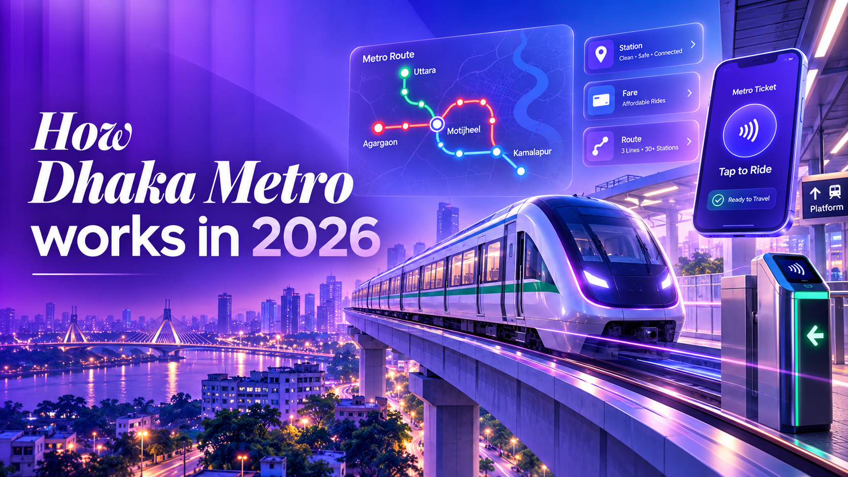
How Dhaka Metro Works in 2026
A complete technical and passenger guide to Dhaka Metro in 2026: from smart card ticketing, TVM recharge, and automated fare gates to CBTC signalling and train control.


15 min read
Key Takeaways
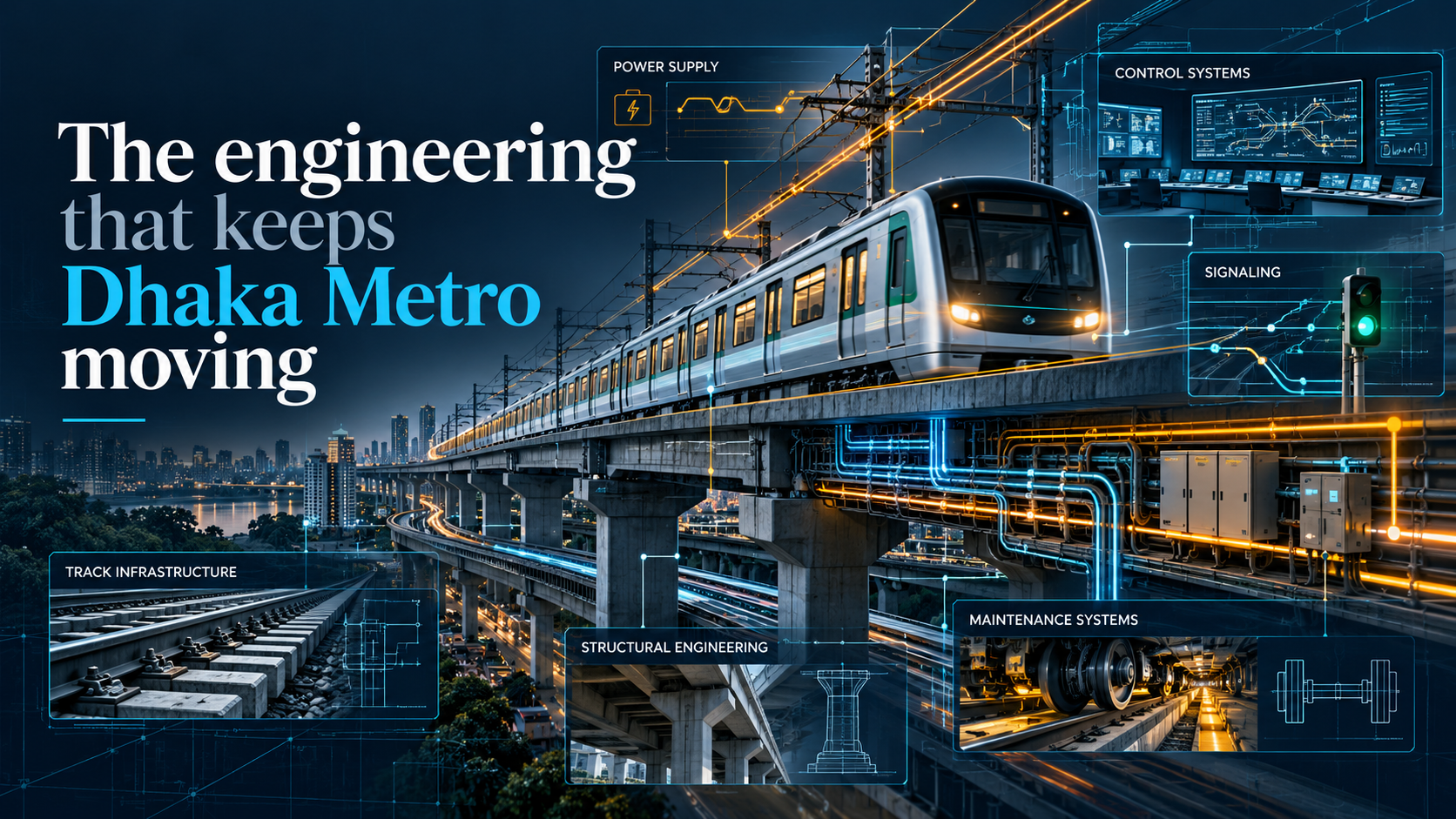
Power rolling stock structures control communications and the work between them
Watch a train glide into a station. It is tempting to call the whole thing a software system because screens and automation are easy to notice. Then look above the roof. A physical collector has to meet a live overhead conductor. Below the carriage, steel wheels and brakes have to turn control decisions into movement.
Now imagine the train stops correctly, but one door cannot prove that it has closed. The important question changes from “Can we leave on time?” to “What is permitted to happen next?” That imagined fault reveals why a metro needs several engineering disciplines and carefully designed interfaces between them.
This article separates confirmed Line 6 equipment from illustrative engineering principles. The fault examples are teaching scenarios, not reports of incidents in Dhaka.
Confirmed for Dhaka: Line 6 uses 1,500 V DC overhead traction power. It is not a third rail system. DTCA’s specification and the system integrator’s commissioning release both identify overhead supply.
Figure 1 Corrected engineering overview with 1,500 V DC overhead supply and a pantograph Energy and information links are conceptual
Illustrative energy path: utility AC is transformed and rectified at a traction substation; the overhead conductor supplies the train through its roof mounted pantograph. Onboard traction equipment converts and controls electrical energy for the motors. This simplified path omits protective switchgear, return circuit details and isolation arrangements.
The diagram separates energy from information. A train-control message can authorize movement, but it cannot provide the electrical energy that turns the wheels. Treating those two paths separately helps explain why both power engineering and control engineering are necessary.
The overhead wire is the visible supply connection, but an electrical circuit needs a return path as well. In a typical DC railway, the return arrangement includes the running rails and associated conductors. Its engineering involves insulation, bonding, protection and unwanted current paths. The exact Line 6 circuit and maintenance isolation boundaries require project drawings; the illustration intentionally leaves them out.
Power distribution also needs to be observable. SCADA stands for Supervisory Control and Data Acquisition. In railway applications it can bring equipment status, alarms and permitted control actions to operating personnel. Siemens describes these monitoring and control functions in its rail electrification material. This explains the role, not the identity of Dhaka’s SCADA software.
Imagine an illustrative substation fault. The useful questions are which equipment changed state, which area is affected and what authorized action can restore service safely. A diagram that shows only a grid and a train cannot answer them. Power engineering includes the ability to detect and isolate trouble, coordinate maintenance and establish what has actually been energized or disconnected.
These responsibilities do not disappear because driving is automated. A train can have valid movement information and still lack the power needed to run. Equally, an energized railway does not by itself grant any train permission to move.
Rolling stock engineering concerns the vehicle itself: its body, bogies, wheelsets, suspension, traction, brakes, doors and onboard equipment. A command to accelerate has to become motor torque, then usable force at the wheel and rail contact.
Illustrative mechanism: traction equipment regulates the motors while suspension controls the vehicle’s response to the track. Train load and available adhesion influence performance. A control design must accommodate those conditions rather than assume every trip has the same passengers, weather and braking response.
Braking also connects disciplines. Electrical braking can recover some kinetic energy, while friction braking remains important for the required braking function. How the methods blend and what happens during equipment failure depend on the vehicle design. L&T’s release confirms regenerative energy storage as a Line 6 project feature; it does not give a measured energy saving for an ordinary passenger trip.
When motors operate regeneratively, some of the train’s kinetic energy becomes electrical energy. Recovery is only useful if the electrical system can accept that energy. The destination might be another consuming train, suitable storage or a reversible substation, depending on the railway design. Research on electric transit systems describes these different recovery approaches.
For a simplified example, one train brakes while another accelerates. Their power demands can complement each other. At another moment, there may be less demand available to receive recovered energy. This is why “the train has regenerative braking” and “all braking energy is reused” are different claims.
A practical design also has to provide the required braking when regenerative recovery is limited. Vehicle controls, friction brakes and electrical limits therefore need coordinated behaviour. The exact blending strategy and fallback modes are vehicle-specific. The reference establishes general energy-recovery principles, not a measured efficiency or control strategy for Dhaka.
There is a useful systems lesson here. Energy saving is influenced by how vehicles, electrical infrastructure and service operation interact. An impressive component does not automatically produce the same saving in every operating condition. Measured results need a defined baseline and actual operational data.
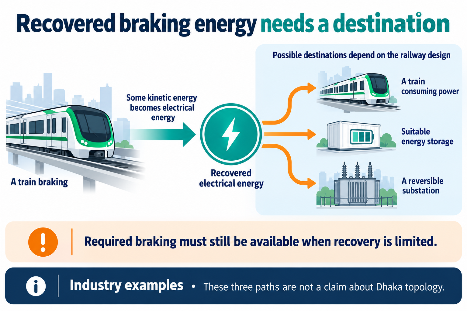
Figure 2 Possible destinations for recovered braking energy depend on the railway design Not a diagram of Dhaka topology
The elevated structure does much more than hold the train above traffic. Its alignment and track support establish the geometry on which movement depends. The platform edge and door openings have to work with the train envelope and stopping position.
Illustrative interface problem: suppose a platform opening is designed without checking the vehicle doorway location. Both pieces might be well made, yet passengers would still face a boarding problem. Civil, track, vehicle and door teams therefore need coordinated dimensions and tolerances.
Figure 3 Track vehicle and platform interfaces require coordinated geometry No Dhaka dimensions are asserted
The same reasoning applies to routes through the station. Stairs, lifts, escalators, circulation space and emergency access have to serve real crowds. A railway can have sophisticated signalling and still offer a poor journey if passengers cannot move through its stations comfortably.
In ordinary business software, a late report may still be useful. A control function has a tighter relationship with time: a correct result delivered after its required deadline can be unusable. Real time engineering is about meeting specified timing requirements reliably, not simply owning a fast processor.
Consider an illustrative controller receiving speed information. It needs to know whether the information is recent enough for its task. A number can be syntactically valid and still be stale. An update can arrive twice, or arrive after a later update. The design must establish which state is current and what to do when required information is no longer trustworthy.
Figure 4 A control function considers state and information timing No Dhaka deadlines are asserted
Embedded systems connect that software to physical inputs and outputs. A sensor reading, a motor command and a reported device status form a chain that can be tested at several levels. Testing an application screen is not sufficient evidence that the physical equipment responded correctly.
These principles do not identify Dhaka’s processor, programming language or operating system. They explain why a railway controller needs predictable interfaces, bounded timing assumptions and defined fault behaviour. Choosing those details is an engineering decision that depends on the particular subsystem and its requirements.
DMTCL lists ATO, ATP and ATS within its CBTC arrangement. Their names describe different responsibilities. Automatic Train Operation supports automated driving; Automatic Train Protection enforces safety constraints; Automatic Train Supervision oversees service operation. Automation by itself does not prove unattended or driverless operation.
Illustrative localization: a CBTC design can combine onboard distance or speed measurement with known trackside references, then communicate position to control equipment. Hitachi publishes an example of that architecture for another railway. This is useful for understanding the principle, not evidence that Dhaka uses the same transponders, sensor mix or algorithms.
Movement authority is the permission to proceed within specified limits. It is different from a timetable request to depart. A controller can want a train to recover delay while the protection system still constrains how far and how fast it may move. That distinction prevents service pressure from becoming a substitute for safety permission.
A distance estimate can be precise-looking without being exact. If movement is inferred from wheel rotation, the calculation depends on the relationship between wheel rotation and travel along the rail. Small errors can accumulate. A known reference can help correct the estimate, but information between references still has uncertainty.
Sensor fusion means combining available measurements or references in a way that supports a better estimate than relying on one source alone. It is not a magic process that makes every measurement true. A useful design considers disagreement, missing updates and how much confidence to place in the result. Hitachi’s published CBTC example illustrates onboard measurement corrected by trackside reference information.
For a software reader, the lesson is to distinguish an estimated value from an unquestionable fact. “Position is available” does not necessarily mean it has the freshness and confidence required by every consumer. Passenger information and movement protection can have different requirements for how that information may be used.
In a simplified fixed-block explanation, the route is divided into predefined sections used to regulate occupancy and separation. A moving-block principle uses train movement information to support a protective limit that changes with the operating situation. Alstom’s CBTC overview describes moving-block or optimized fixed-block approaches; the details depend on the product and railway.
The benefit is more flexible use of track space, subject to the applicable protection design. It is not permission to put trains at any arbitrary distance from each other. Braking capability, position uncertainty and the required protective arrangements still matter.
Capacity also depends on what happens at stations and terminals. If boarding takes longer, a following train cannot make that time disappear by knowing its position more accurately. A turnback arrangement can constrain the next departure even when signalling could support shorter separation elsewhere. Signalling, station dwell and track layout therefore need to be considered together. This is a general capacity explanation, not a claim about Dhaka’s current maximum frequency.
Figure 5 Position information supports movement permission A conceptual CBTC explanation rather than a Dhaka signalling plan
An open-loop approach would apply a preselected braking command and assume the train finishes at the intended point. A feedback approach observes movement, compares it with the target and adjusts the command as the train progresses. That is the control principle behind the next illustration; it is not an as-built Line 6 block diagram.
Position uncertainty and braking behaviour both matter. Wheel-based movement estimates can accumulate error, and the train’s response can vary with conditions. Suitable reference information and updated measurements help a control system work with those uncertainties. The permitted safety envelope still constrains what an automatic driving function may request.
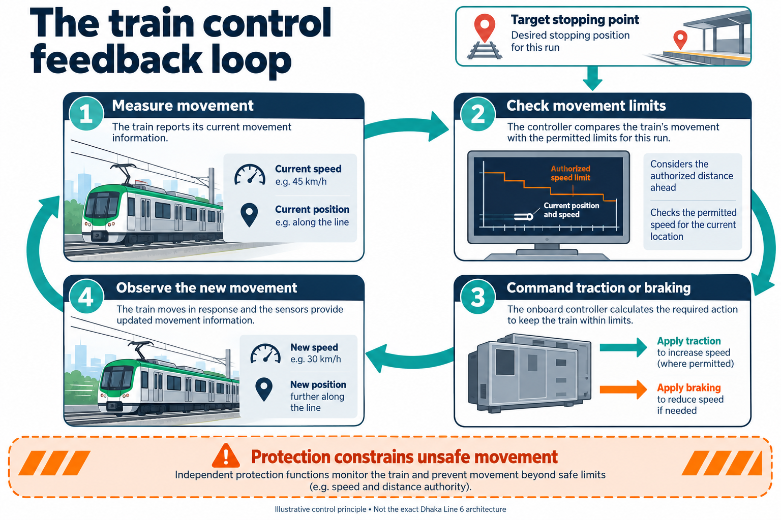
Figure 6 A conceptual feedback loop connecting measurements movement limits and physical response Not Dhaka configuration data
Why can a train not simply brake at the same marker every time? Because stopping is affected by its initial speed and available deceleration. The following graph isolates that relationship using a deliberately idealized model. With constant deceleration and no reaction delay, braking distance is proportional to the square of initial speed.
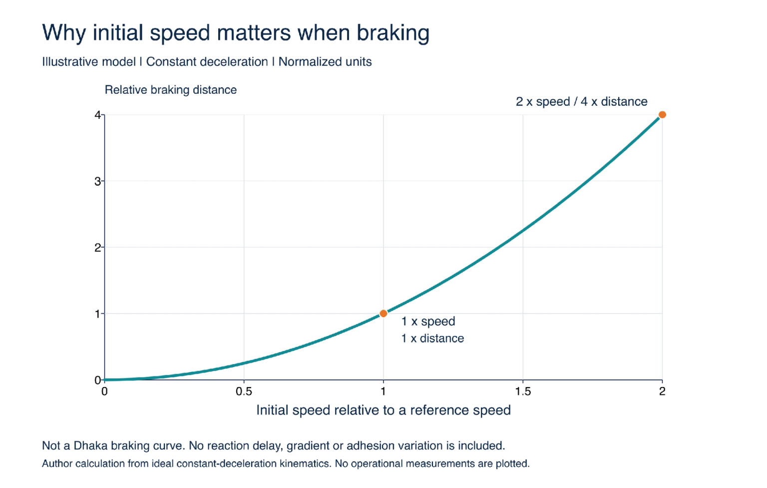
Figure 7 Illustrative normalized braking distance at constant deceleration Not a Dhaka braking curve No reaction delay gradient or adhesion variation is included
A train starting at twice the reference speed needs four times the ideal braking distance in that model. That does not mean an actual metro uses a fourfold safety margin or that the graph predicts any station’s stopping distance. It demonstrates why a small speed error cannot always be treated as a small position error.
Comfort adds another constraint. Passengers standing in the aisle feel changes in acceleration, especially abrupt changes often described through jerk. A useful operating profile must work within the required protection constraints while producing an acceptable ride. Precise stopping is therefore not simply the strongest possible brake application at the last moment.
A door opening feels like a single action to the passenger. Engineering has to consider the stopped train, the boarding position, the permitted side and feedback from the door equipment. A coordinated door system depends on shared state, not simply matching two clocks.
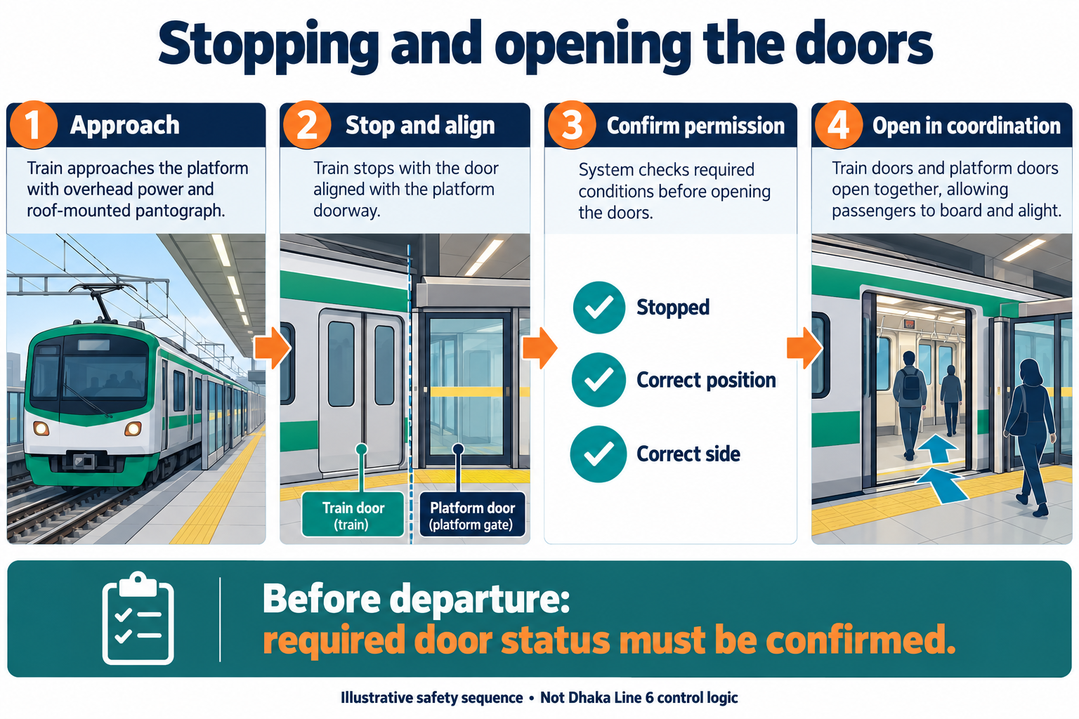
Figure 8 A teaching sequence for the interface between train stopping and doors The checks shown are illustrative rather than Dhaka configuration data
Illustrative fault: a closing command is issued, but the required closed status is not received. “Command sent” is not equivalent to “door safely closed”. A system needs a defined response, and staff need an authorized way to diagnose and recover. The precise degraded mode and override rules must come from the operator’s procedures; they cannot be reconstructed from a passenger’s observation.
The door example can be represented as a state machine: stopped and awaiting release, released, open, closing and confirmed ready for departure, with additional fault states as required. The value of this model is that transitions have conditions. A command to close is one event; confirmed closure is another.
That distinction can be reviewed and tested. What happens if a status message is delayed? What happens if a power cycle occurs while equipment is between states? Which operator actions are permitted, and what information must be presented? A diagram or table is useful when it exposes an ambiguous transition before equipment reaches the platform.
Safety engineering also asks whether a failure is detected and what state the system reaches afterwards. “Fail safe” does not mean every failure has no consequence or every subsystem responds identically. It means the required safe response has to be defined for the hazard and operating context. Specific emergency and degraded procedures must come from the railway’s approved arrangements.
A metro needs train movement data, passenger messages, equipment alarms and staff communication. These have different urgency and safety implications. A stale arrival estimate can confuse a passenger; missing information needed for movement protection calls for a defined safety response.
Illustrative design principle: systems need controlled interfaces and appropriate separation, access management, monitoring and failure handling. A railway communications network should not be imagined as one ordinary office Wi-Fi network doing everything. Conversely, merely naming a radio technology tells us little about redundancy, cybersecurity configuration or safe degraded operation.
Figure 9 Inputs permitted outputs and physical feedback form an industrial control loop Illustrative architecture
Passenger information also needs operational context. Route data, audio selections and display content should agree. An announcement controller can play a correct recording at the wrong station if the journey state is wrong. Integration testing must therefore verify the whole chain, not only the loudspeaker.
A Programmable Logic Controller, or PLC, is an industrial controller used to process inputs, execute logic and update outputs. Siemens’ documentation describes cyclic program processing as one execution model. This helps explain how industrial equipment can repeatedly evaluate conditions and act on them.
An interlock is the dependency that permits an action only when its required conditions are satisfied. The concept can be implemented using different kinds of equipment and architecture. Seeing a door move does not tell us that a particular PLC brand, scan time or program is behind it.
A controller also needs appropriate inputs, output behaviour, diagnostics and assurance for its intended role. Putting a safety-related rule into ordinary application code is not, on its own, proof of an adequate safety system. The equipment and its verification have to match the requirements. No specific PLC installation or safety-controller configuration is asserted for Dhaka here.
An event-driven passenger information service might publish a station-progress event to a display function and an audio function. That can be a useful way to keep routine messages coordinated. It does not follow that the same event is sufficient authority to open a door or move a train.
Different interfaces carry different responsibilities. Operational data can support service regulation; passenger information helps people understand the journey; safety-related information is used within the relevant protective design. Copying a software architecture pattern from one role into another without reviewing its timing and failure assumptions would be careless engineering.
Security has a similar boundary. Knowing which device sent a message is one question; knowing that it is authorized for the requested action is another. Controlled access, configuration management and trustworthy records matter across the railway. We do not need to name a firewall brand or claim a particular network segmentation scheme to explain why those controls are necessary.
The following matrix is an illustrative allocation of engineering concerns. Real contracts and organizational responsibilities can divide them differently. Its purpose is to show why a fault at one interface often needs more than one team.
Table 1 Engineering concerns and interfaces An illustrative responsibility map
| Discipline | Primary concern | An interface it must coordinate |
|---|---|---|
| Electrical power | Supply, protection and isolation | Traction equipment and operations |
| Rolling stock | Vehicle movement and onboard equipment | Track, power, control and platform doors |
| Civil and track | Structures, geometry and support | Vehicle envelope and boarding openings |
| Control and embedded software | State, timing and permitted commands | Sensors, actuators and protective functions |
| Communications and security | Useful, authorized and timely information | Operational, passenger and control services |
| Operations and maintenance | Service decisions and verified recovery | Equipment status, staff procedures and fault evidence |
A recurring door fault, for example, could involve alignment, a mechanical issue, a sensor or a control interface. An alarm names an observed condition; it does not always identify the root cause. Useful diagnosis follows the evidence across the boundary rather than handing the problem back and forth because each component passed its own isolated check.
Figure 10 Maintenance includes verification of function and interfaces Illustrative workflow rather than Dhaka procedure
Good equipment ages. Doors cycle repeatedly, wheel profiles change and electrical connections need attention. Maintenance teams need inspection plans, fault records, access to equipment and a way to verify that repairs restore the intended function.
Consider three illustrative acceptance tests: a recharge interrupted before card update, a train arrival estimate changing after a delay, and a door status missing before departure. Each asks whether the system recognizes an incomplete state and responds appropriately. They are suggested engineering questions, not claims that a particular Dhaka test script has been published.
Table 2 Questions for integration testing Proposed examples rather than Dhaka test records
| Illustrative scenario | Evidence to inspect | Question the test should resolve |
|---|---|---|
| Card removed during value update | Payment, card result and transaction state | Can uncertainty be resolved without duplicate value? |
| An old movement message arrives late | Message age, ordering and accepted state | Does stale information replace a newer state? |
| Required door status is missing | Command, feedback and permitted next state | Is the defined response enforced and visible? |
| Return journey is selected | Route direction, screen and audio selection | Do all passenger messages match the new journey? |
| A repaired device is returned to service | Relevant function and interface results | Has the intended function been verified after repair? |
Imagine a hypothetical software update that changes how a next-station event is produced. A unit test may show that the new function emits the expected value. Integration testing still needs to establish that the display and audio consume it correctly, including at a terminus and on the return journey. If the interface is safety-related, its assurance requirements are different again.
The same principle applies to hardware repair. Replacing a component is an intervention, not proof of restored service. The relevant function and interfaces need verification under the applicable maintenance procedure. Fault history is valuable because an intermittent problem can disappear during a short inspection and return under operating conditions.
For readers wanting to study this field, begin with one physical flow. Trace a card recharge to learn transaction consistency. Trace a train stop to learn feedback, measurement uncertainty and protective constraints. Trace a door cycle to learn state machines and permissions. Then investigate the interfaces that connect them. That approach turns a long list of engineering subjects into a set of concrete questions.
The strongest lesson for a software engineer is about interfaces. A database transaction, a motor command and a passenger’s movement happen on different timescales. Clear ownership, trustworthy feedback and defined recovery connect them. The train reaching the right place is only part of success; the station and people around it must be ready for the next step too.
A complete technical and passenger guide to Dhaka Metro in 2026: from smart card ticketing, TVM recharge, and automated fare gates to CBTC signalling and train control.

The Netherlands has near-universal English fluency and a persistent shortage of senior engineers in AI, MLOps and cloud infrastructure. Here is why Dutch companies are moving to remote development teams, and what to verify before committing.

HIPAA and GDPR overlap on security controls but diverge on consent, individual rights and breach notification timing. Here is the technical crosswalk, PHI handling architecture, BAA process and AI governance one dual-compliance HealthTech platform needs.

Ebrahim KhanFounder & CEO
 We’re happy to sign an NDA upon request.